Understanding Cable Tray Ladder Type DWG Designs
In the world of electrical installations, cable management is a crucial component for ensuring safety, organization, and efficiency. One of the most effective solutions for cable management is the use of cable trays, particularly the ladder type. This article delves into the intricacies of cable tray ladder type DWG (Drawing) designs, offering insights into their applications, design considerations, and benefits.
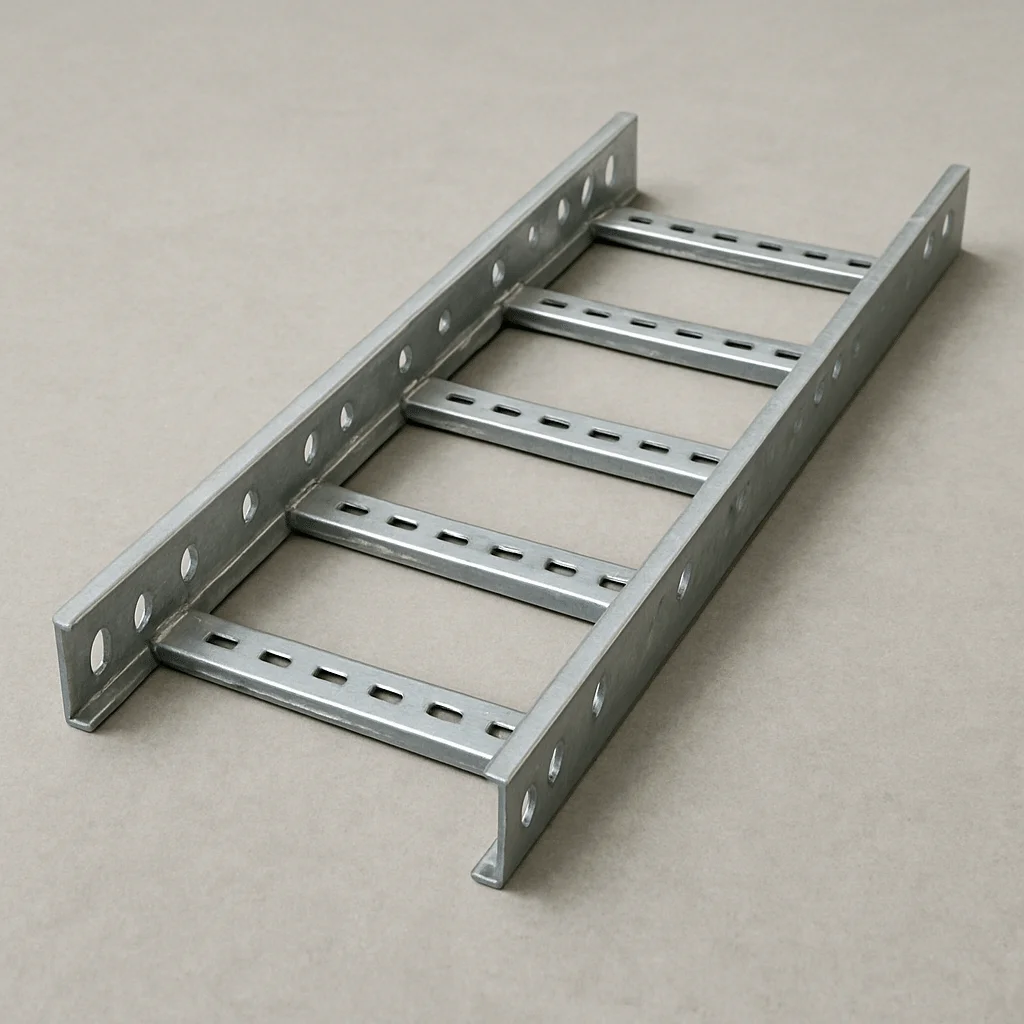
A cable tray ladder type is a structure used to support insulated electrical cables used for power distribution and communication. Its design resembles a ladder, with two longitudinal side rails connected by individual rungs, allowing for easy cable placement and management. This open design aids in cable ventilation and cooling, reducing the risk of overheating.
Applications of Cable Tray Ladder Type
Cable tray ladder types are ideal for environments where cable ventilation is a priority. They are widely used in industrial settings, commercial buildings, and plants where large quantities of power and control cables are present. Their robust construction can support heavy cables over long spans, making them a reliable choice for complex installations.
The Importance of DWG Designs in Cable Trays
DWG (Drawing) designs in AutoCAD or similar software play a vital role in the planning and execution of cable tray installations. These designs provide a detailed representation of the cable tray system, including dimensions, materials, and configurations. They serve as a blueprint for engineers and electricians, ensuring accurate and efficient installation.
Key Elements of Cable Tray Ladder Type DWG Designs
When creating or interpreting a cable tray ladder type DWG design, several key elements should be considered:
- Dimensions and Layout: Accurate measurements and layout plans are essential for ensuring that the cable tray fits within the allocated space and meets all installation requirements.
- Material Specifications: The choice of materials, such as aluminum, steel, or fiberglass, can affect the tray’s durability, weight, and cost.
- Capacidade de carga: The design should specify the maximum load capacity to prevent structural failures and ensure safety.
- Support and Mounting Details: Details about how the tray will be supported and mounted are crucial for stability and performance.
- Compliance with Standards: The design must adhere to industry standards and regulations to ensure safety and compatibility.
Designing Ladder Cable Trays with CAD Software
Ladder cable tray designs in CAD software like AutoCAD or SolidWorks allow for precision and customization. Engineers can create detailed models that simulate real-world conditions and requirements, enabling them to optimize the design before physical installation.
Steps in Creating a Ladder Cable Tray CAD Design
- Define the Project Scope: Understand the specific requirements, such as the type and number of cables, the environment, and any constraints.
- Sketch the Layout: Begin with a rough sketch of the layout, considering factors like cable routing, entry and exit points, and obstacles.
- Select Materials: Choose appropriate materials based on environmental conditions, load requirements, and budget.
- Model the Tray in CAD Software: Use CAD software to create a detailed model, incorporating all dimensions, materials, and configurations.
- Review and Iterate: Check the design for potential issues, make adjustments as necessary, and ensure compliance with standards.
Benefits of Using Cable Tray Ladder Type DWG Designs
by UX Indonesia (https://unsplash.com/@uxindo)
Implementing cable tray ladder type DWG designs offers several advantages:
- Enhanced Organization: The structured design helps in organizing cables systematically, reducing clutter and confusion.
- Improved Safety: By providing a secure pathway for cables, the risk of electrical hazards and tripping is minimized.
- Efficiency and Cost-Effectiveness: Pre-planned designs reduce installation time and labor costs, making them an economical choice.
- Scalability: These designs can be easily modified to accommodate future expansions or changes in cable requirements.
- Aesthetic Appeal: A well-organized cable management system enhances the visual appeal of the installation area.
Conclusão
Understanding cable tray ladder type DWG designs is essential for anyone involved in electrical installations. These designs not only ensure efficient and safe cable management but also offer flexibility and scalability for future needs. By leveraging CAD software and adhering to industry standards, engineers can create effective cable tray systems that meet the demands of modern electrical infrastructure. Whether you’re an engineer, electrician, or project manager, mastering these designs will undoubtedly contribute to the success of your projects.
By incorporating these insights into your planning and execution processes, you’ll be better equipped to tackle the challenges of cable management and optimize the functionality and safety of your electrical installations. Embrace the power of cable tray ladder type DWG designs and elevate your cable management strategies to new heights.